iajuar labs
My first experiences with electronics came in the form of circuit bending: purposefully interfering with existing circuitry with intention to modulate and corrupt sounds.
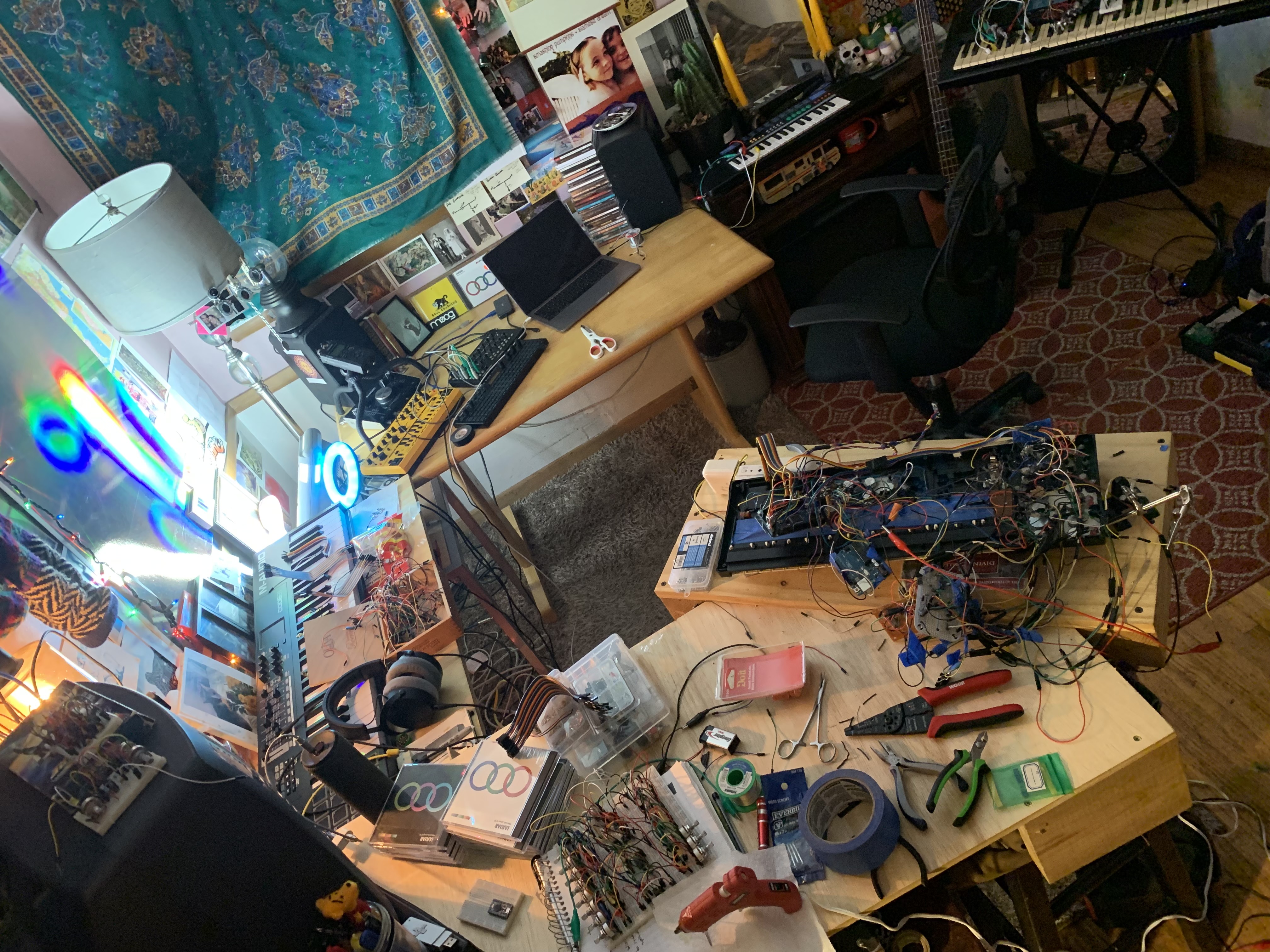
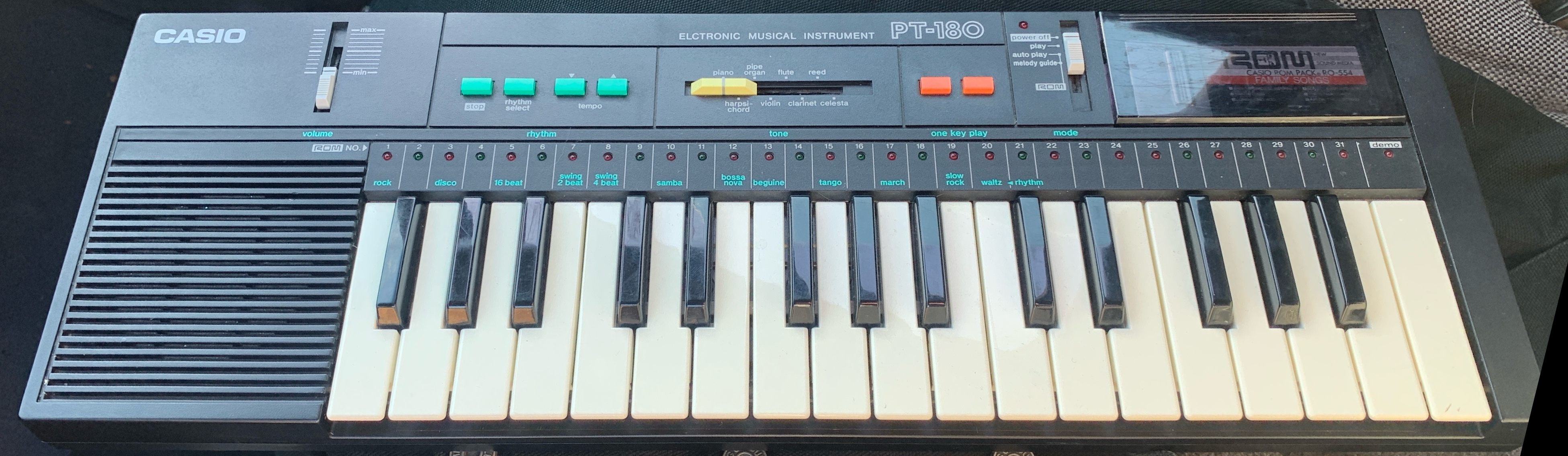
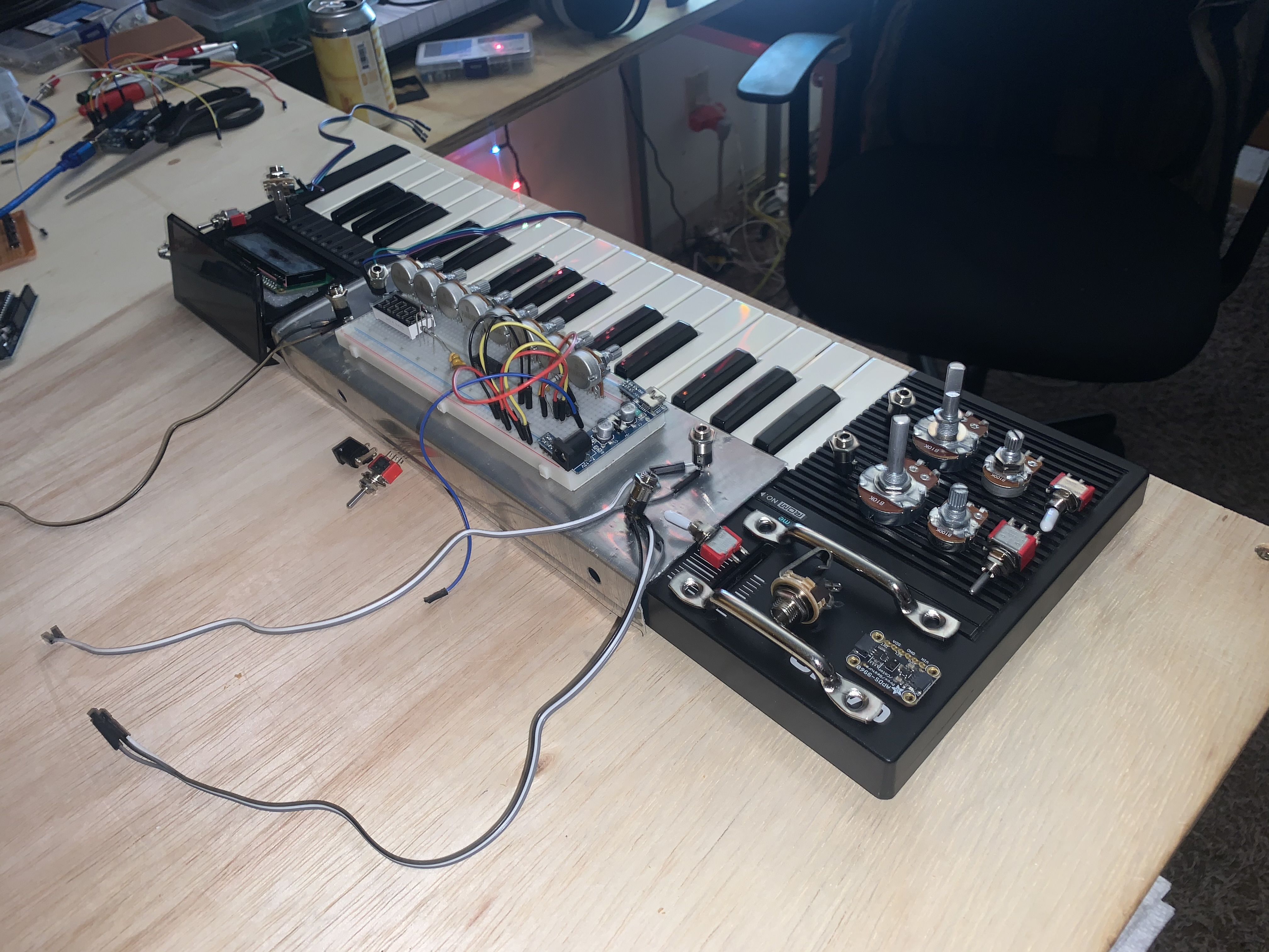
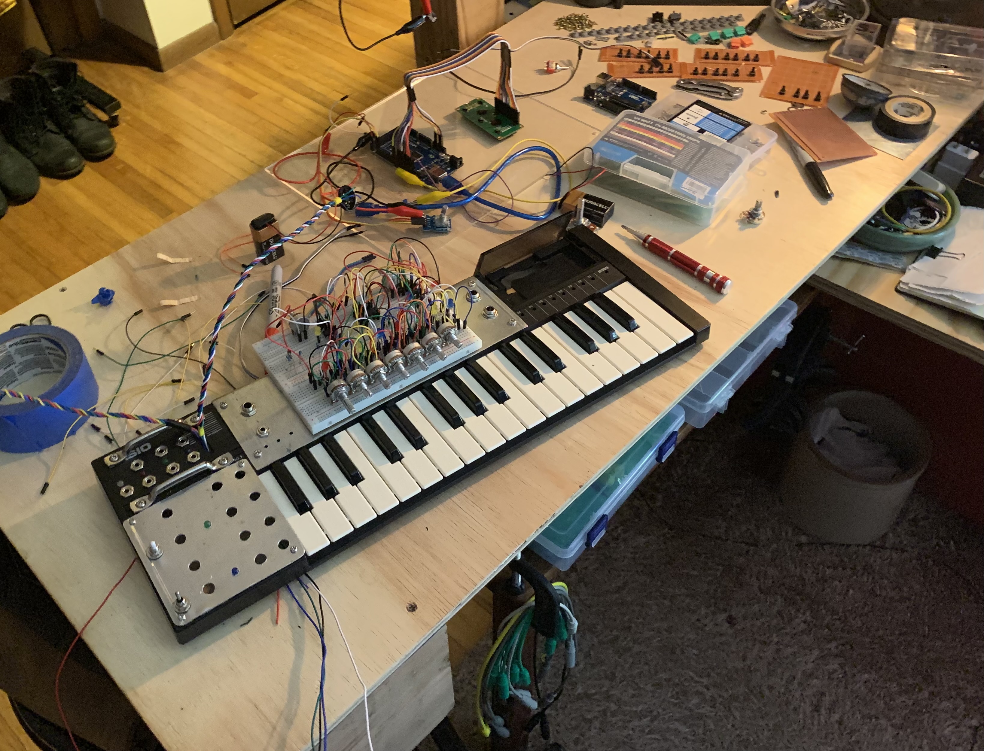
After becoming comfortable with pre-existing circuits, I began testing my own on breadboards. Upon accidentally frying the motherboard of an 80s Casio keyboard, I decided that I wanted to use the case of the newly dead Casio to house all new analog circuitry of my own making:
Before
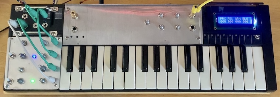
After
Mouseover Components for Info
Oscillators
- Saw Oscillator
- Saw Oscillator Fine Tune
- Saw Oscillator Output
- Saw LFO
- Saw LFO Fine Tune
- Saw LFO Output
- Saw LFO Switch
- Saw LFO Indicator LED
- Square Oscillator
- Square Oscillator Fine Tune
- Square Oscillator Output
- Square LFO
- Square LFO Fine Tune
- Square LFO Output
- Square LFO Switch
- Square LFO Indicator LED
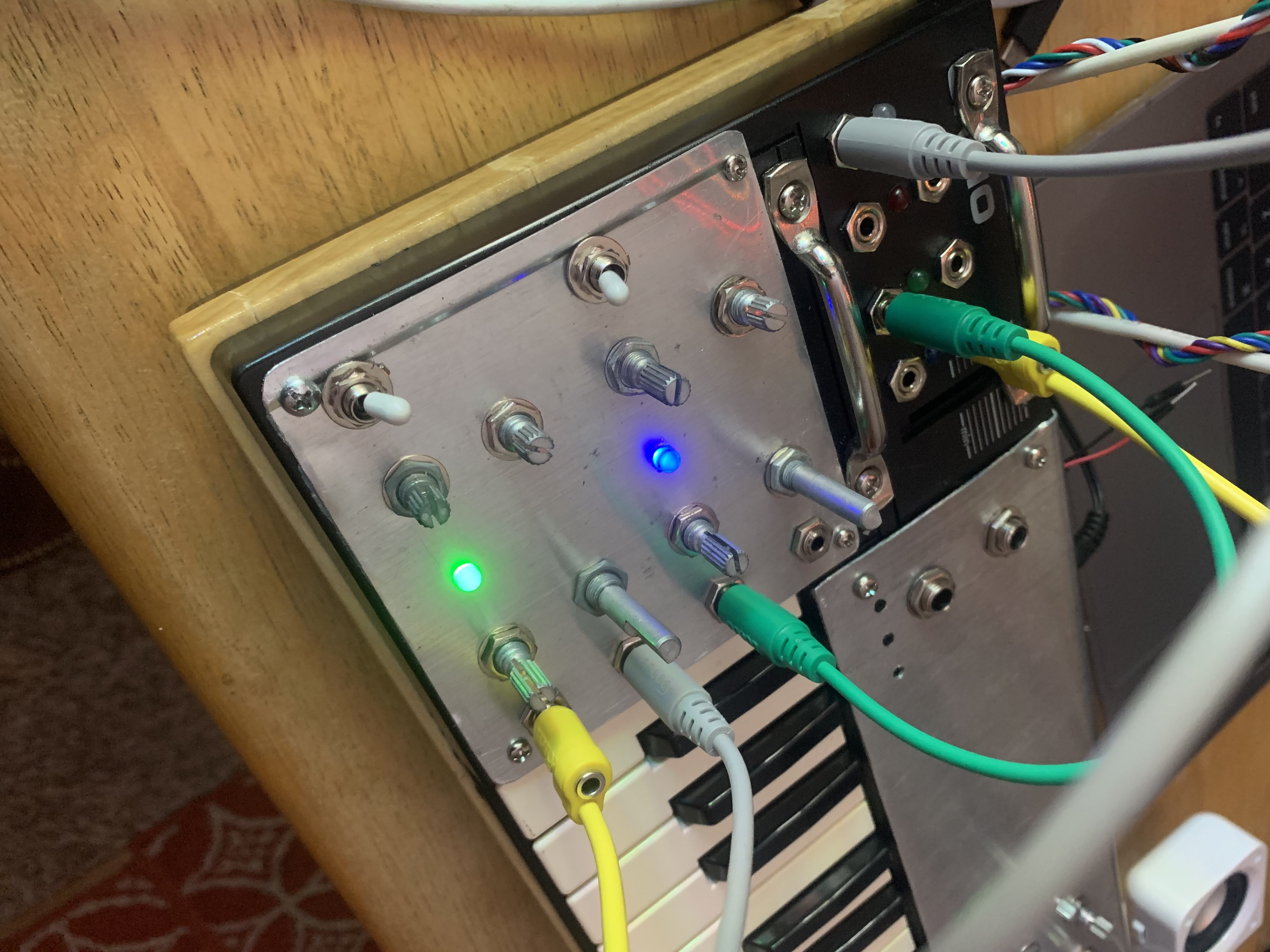
There are 4 oscillators placed on the bottom left control panel: 2 sawtooth, and 2 square wave. Both oscillator waveforms have an LFO which can be activated via switch and an LED indicator light to monitor the rate of oscillation. Each oscillator present is modulated via 2 linked potentiometers - one for coarse control and one for fine tuning.
Demo: Saw oscillator with and without LFO sync
Oscillator Protos
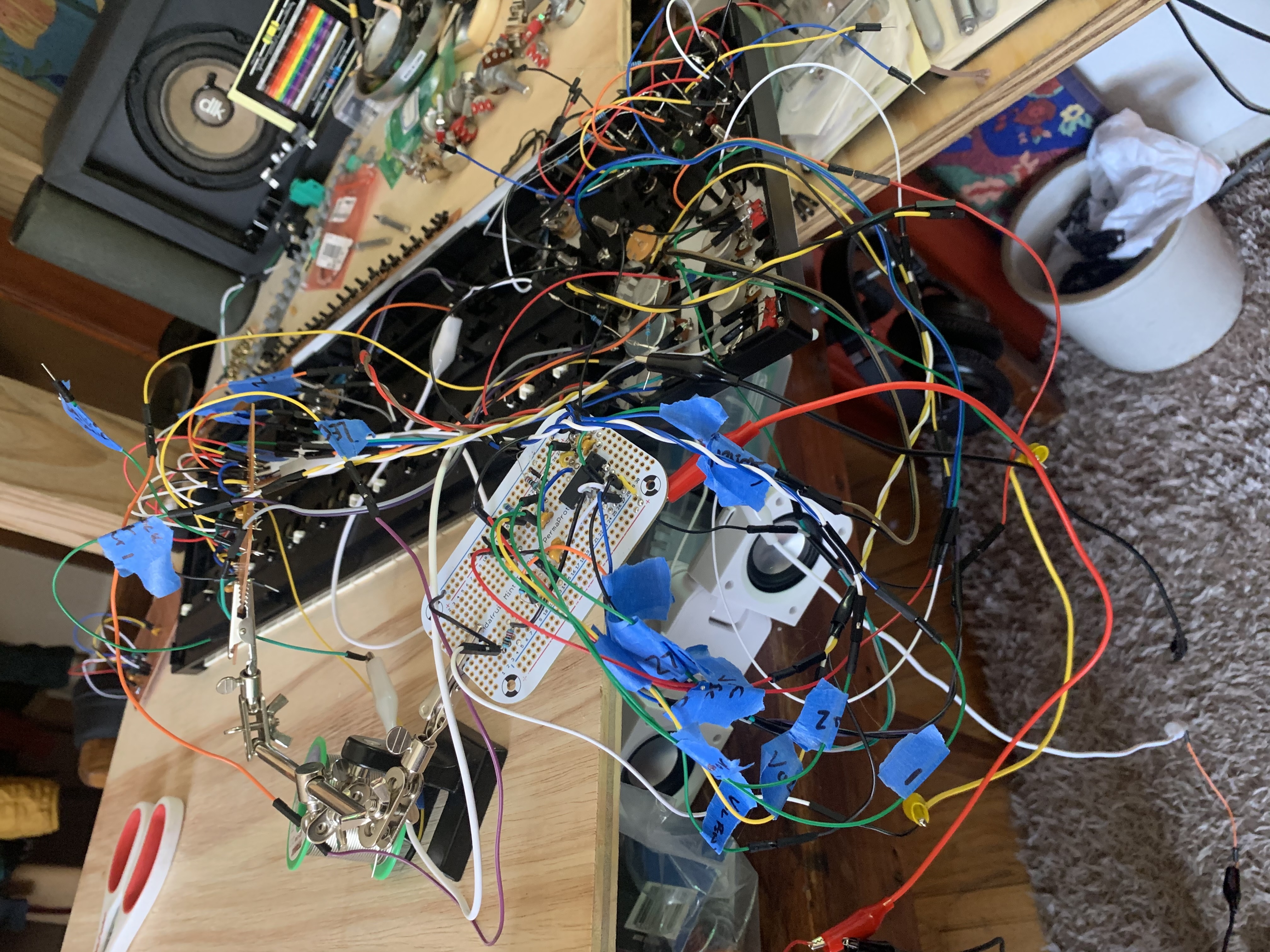
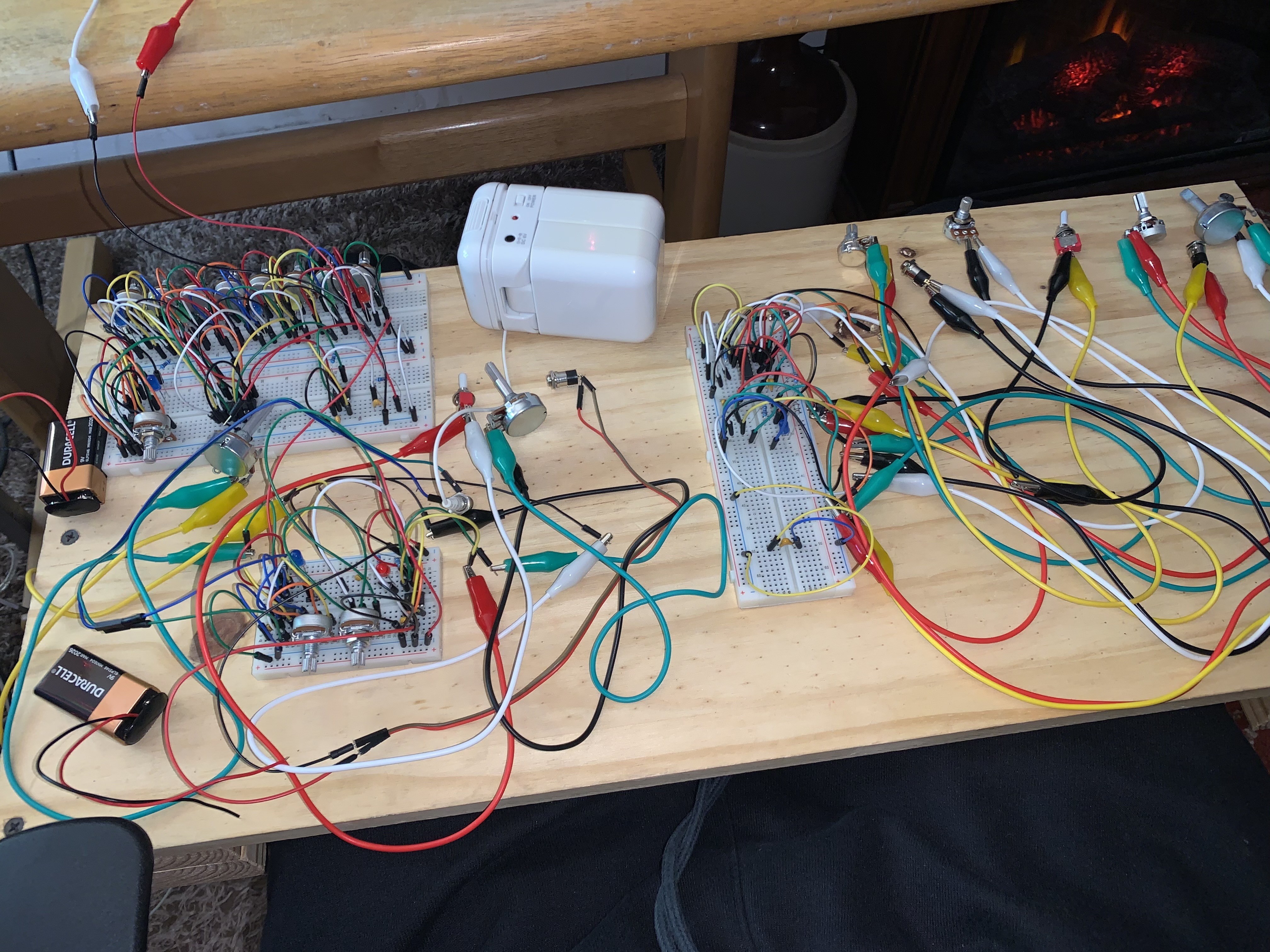
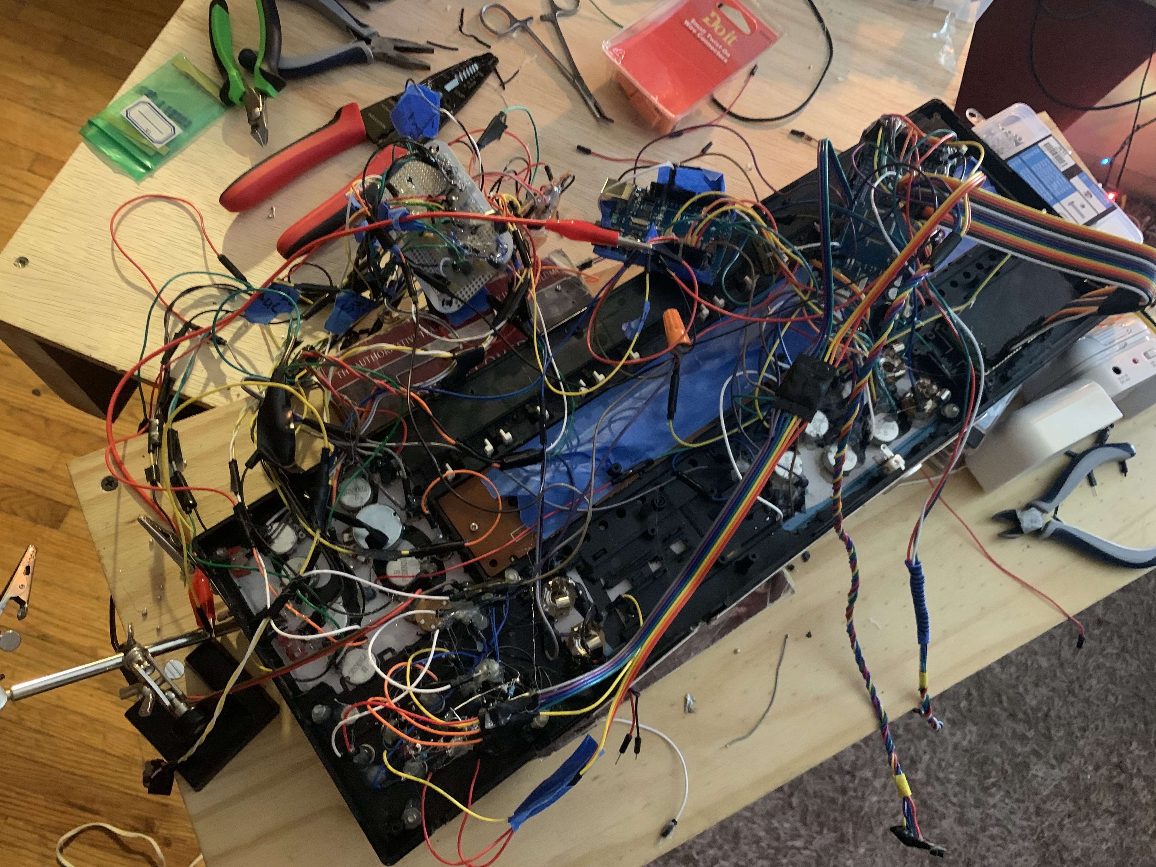
Integration
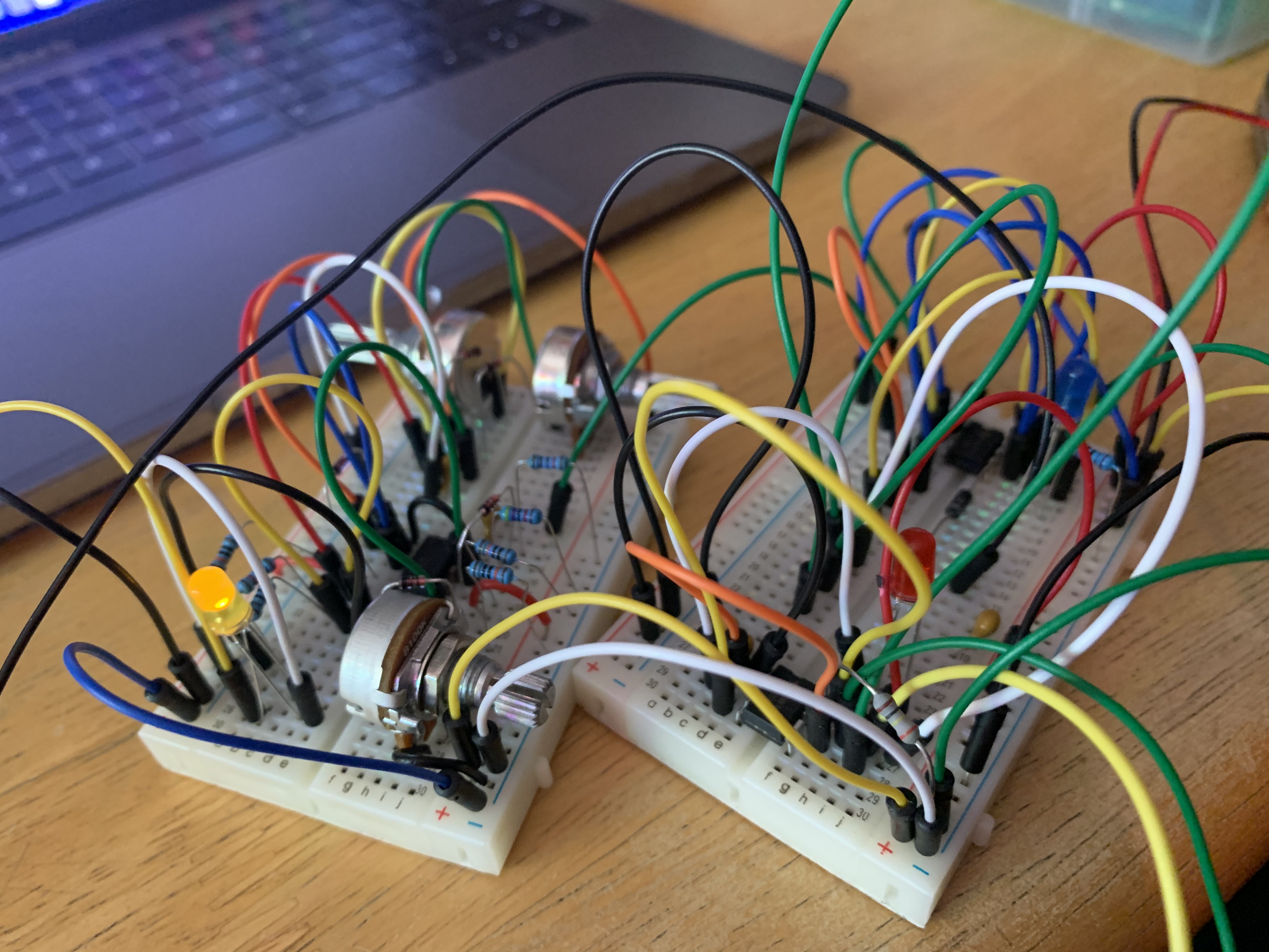
Circuit Testing
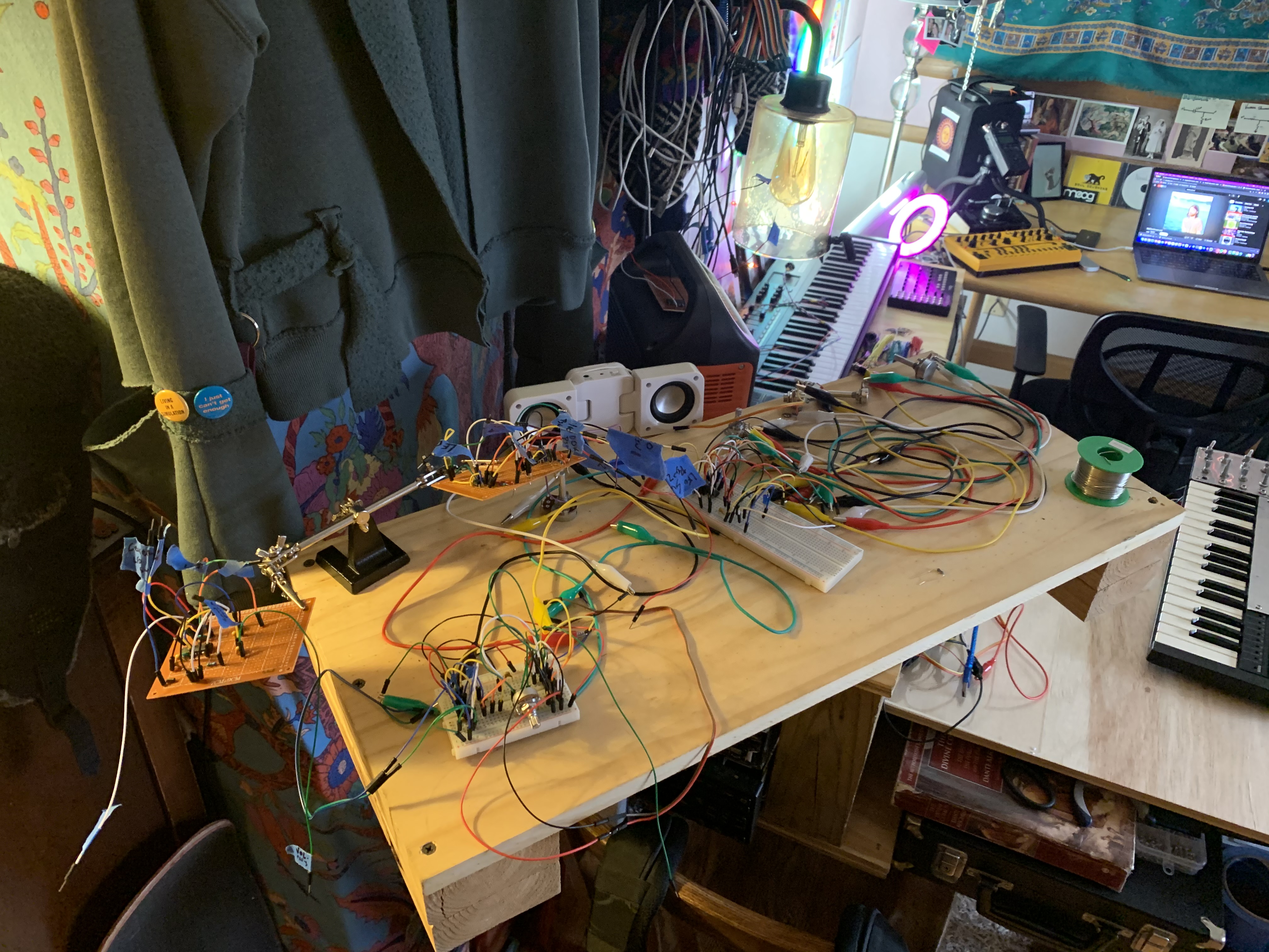
Partially Committed Designs
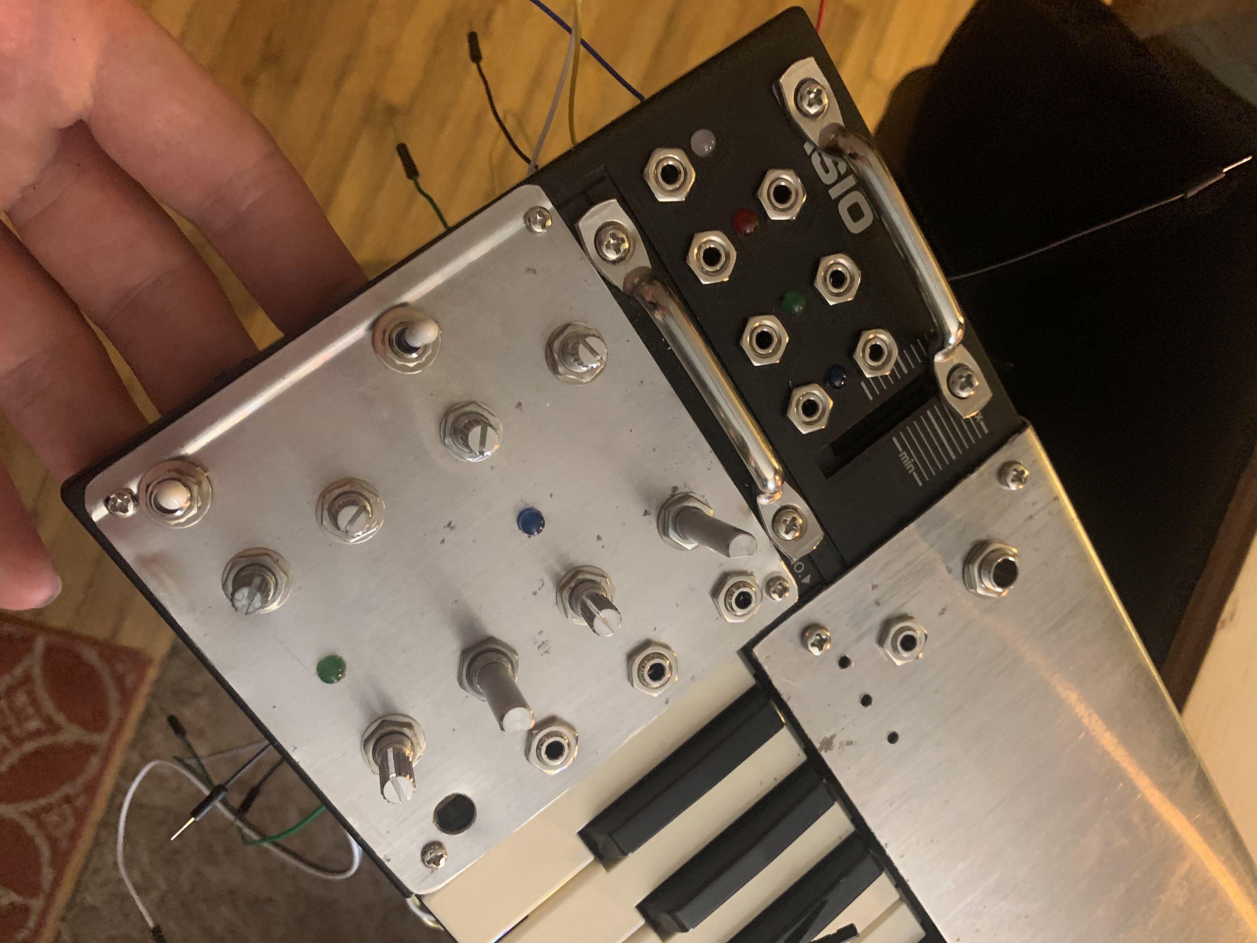
Onboard Hardware Unwired
Onboard Hardware Wired
Sensors
- Ringlight Input: Red
- Ringlight Input: Green
- Ringlight Input: Blue
- Proximity Sensor Output
- Color Sensor Output: Red
- Color Sensor Output: Green
- Color Sensor Output: Blue
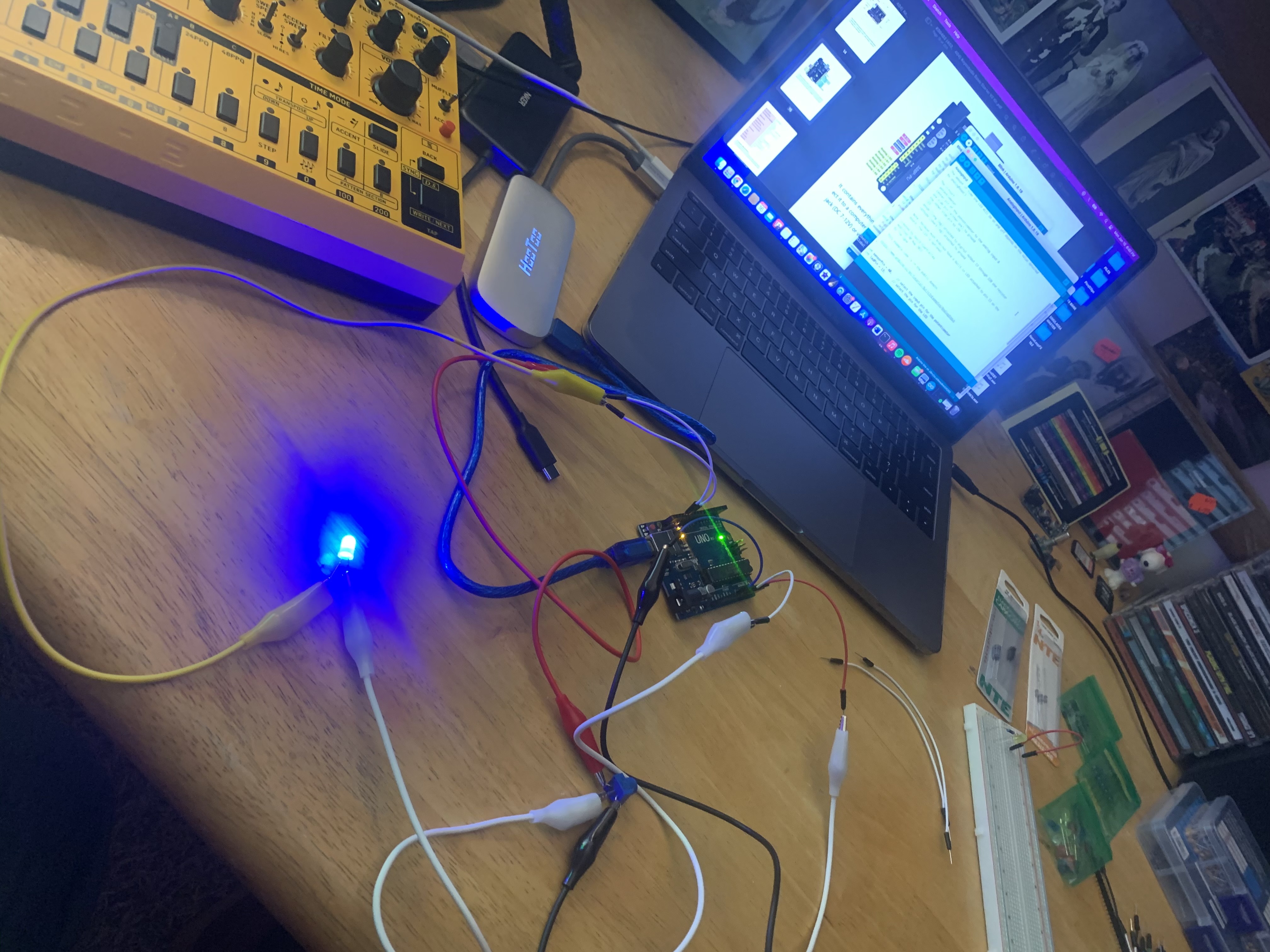
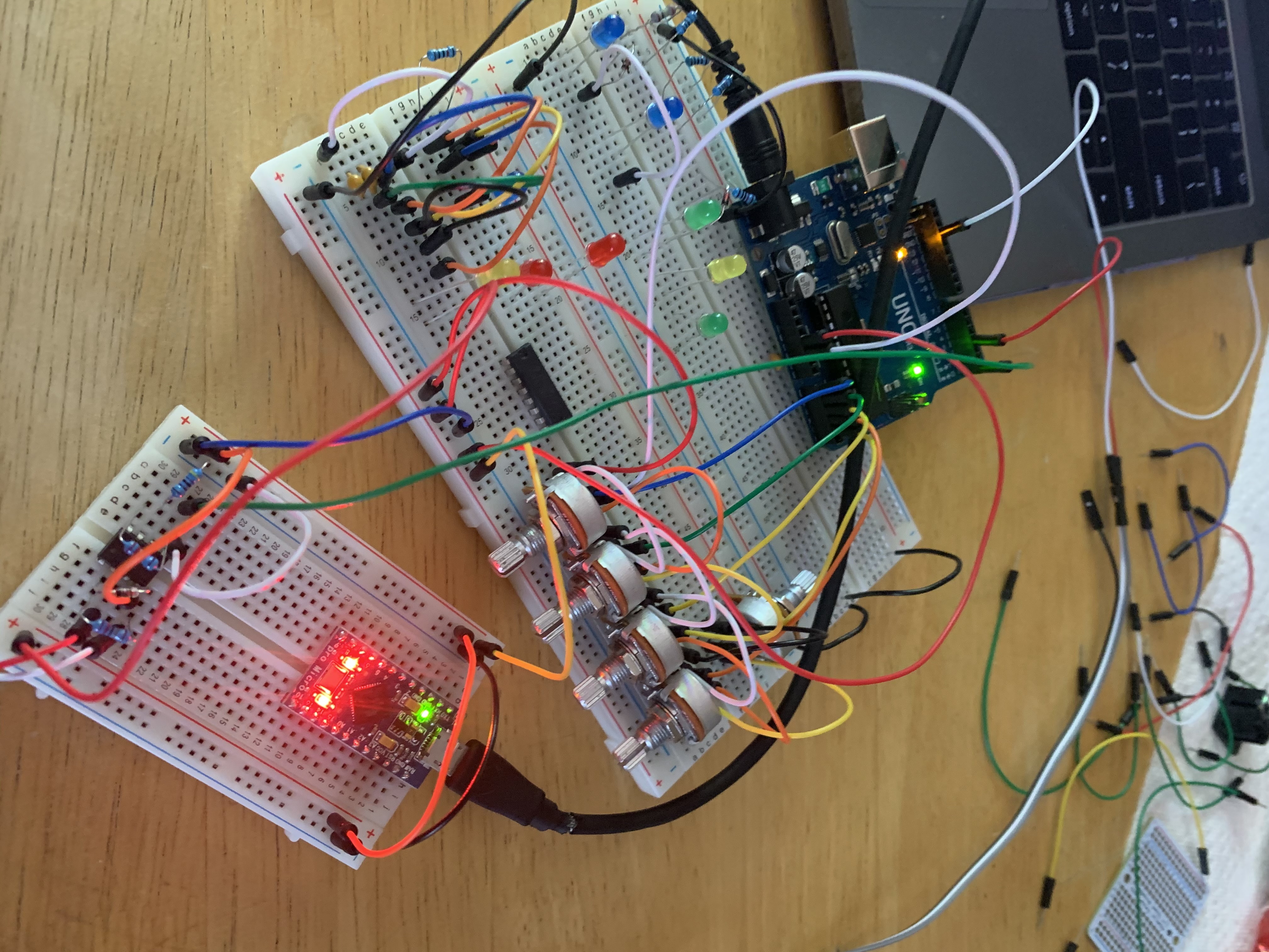
The analog circuitry of the oscillators meets a digital element here where a proximity sensor and LED ringlight are present (not listed above). The sensor (ADPS-9960) measures not only proximity but also digitally quantifies the amount of Red, Green, and Blue light present. Both sensor and ringlight are driven by an Arduino Uno microprocessor—unique about these microprocessors are their ability to take digital measurements and output specified corresponding analog voltages.
Demo: Proximity sensor modulation of oscillator amplitude
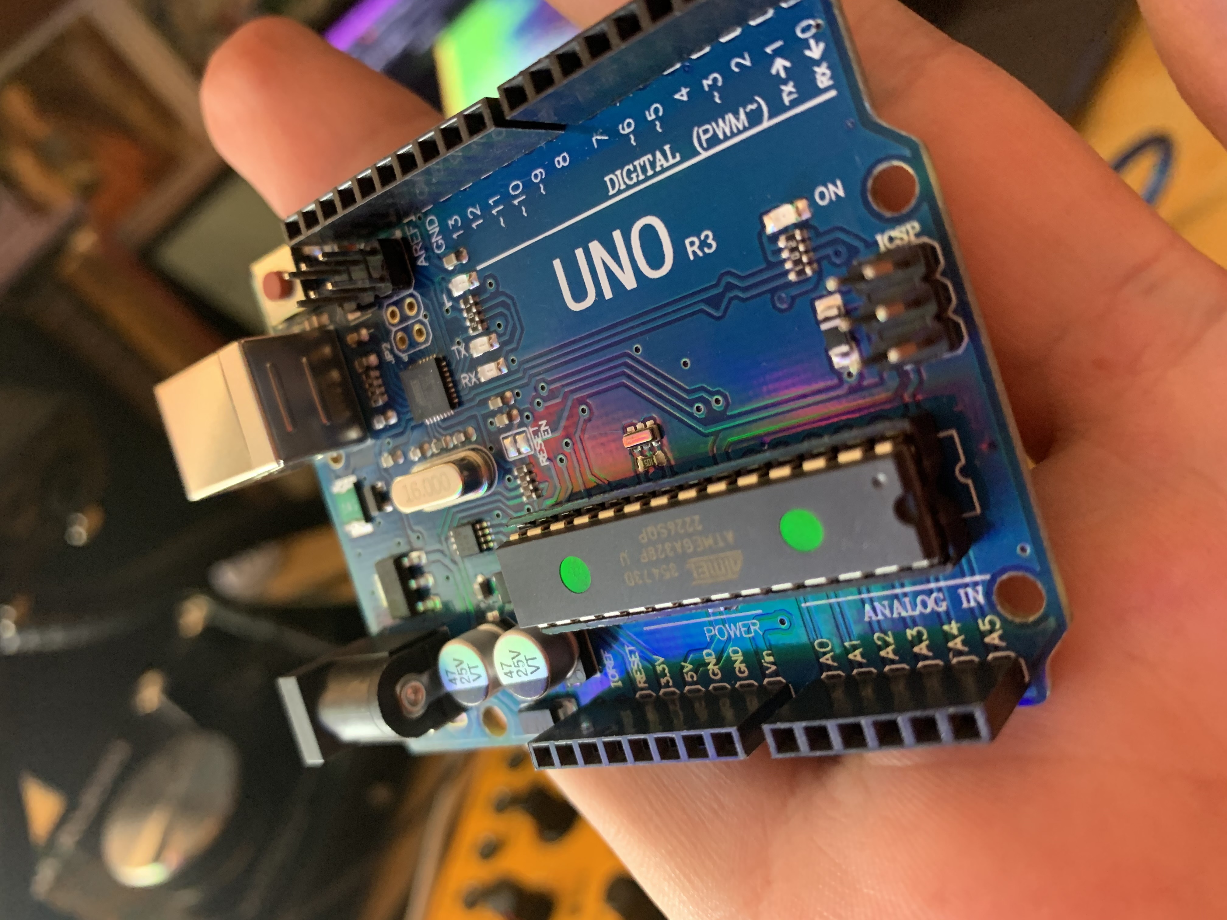
microprocessor
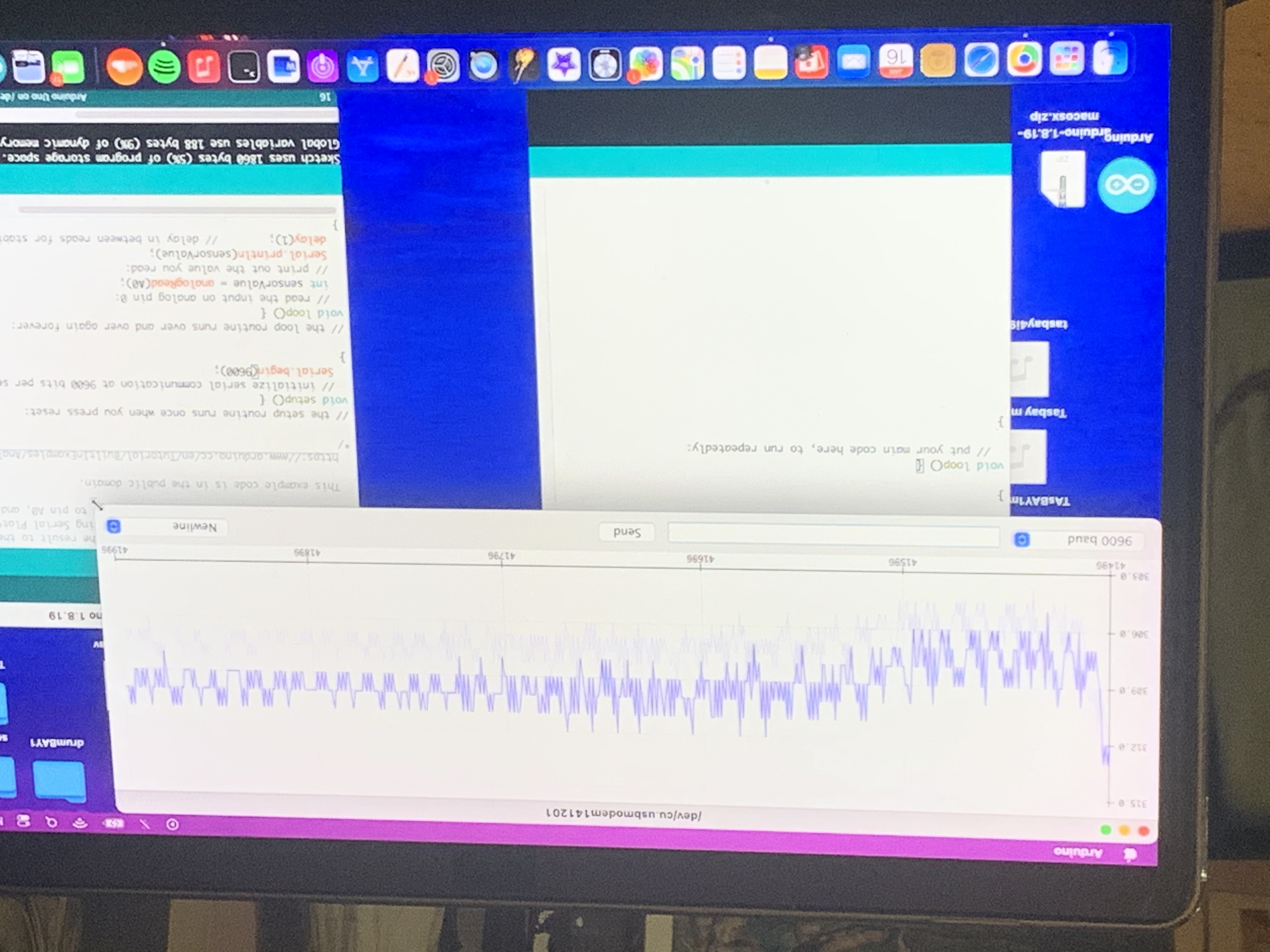
live sensor data
sensors raised above keyboard
live data testing with LED
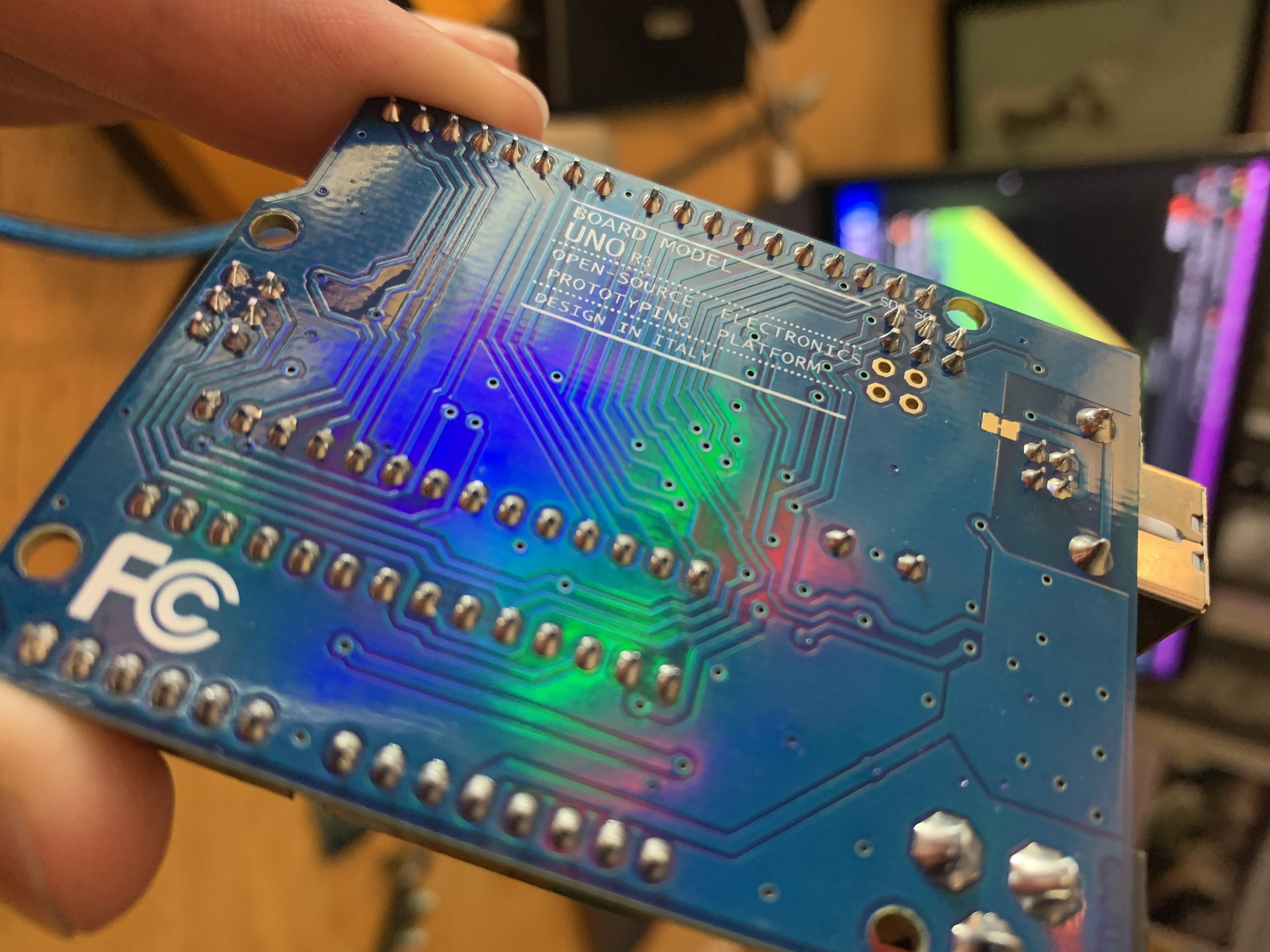
microprocessor soldering points
sensor placement
Outboard Connectivity
- Outboard Jumper to 1/8th Audio
- 1/8th Audio to Outboard Jumper
- Outboard Jumper Connection points
Built into the central control panel, there are two quarter inch jacks which serve as points of flexibility for integrating works in progress. Using the bottom of the two quarter inch jacks as an input, it is possible to use a jumper cable to connect the output of one of the oscillators of the bottom left control panel, and run the analog voltage into this jack. From here we can use the smaller holes placed beneath the jack to connect jumper wires acting as a positive and ground (and negative if necessary) that can then power a breadboard. This allows for the integration of outboard circuitry like extra oscillators and sequencers that is still in development on breadboards.
Demo: Controlling an outboard LED(yellow)
on a breadboard using square LFO (green LED)
Internal Onboard
Central Control Panel Outboard
Internal Onboard #2
Granular
- Granular Pitch Tuner (Chromatic)
- Grain Size 1
- Grain Size 2
- Grain Resonance 1
- Grain Resonance 2
- Granular Output
This is a digital oscillator that is written in C, controlled by a separate microprocessor which also outputs analog voltages. The tuning here is set to a chromatic scale as the pitch potentiometer sweeps through the control range. There are also grain size and resonance parameters which act as a filter to affect the character of this oscillator's sound.
Demo: Granular Oscillator
Digital Granular Synth Proto
Granular Hardware Onboard Unwired
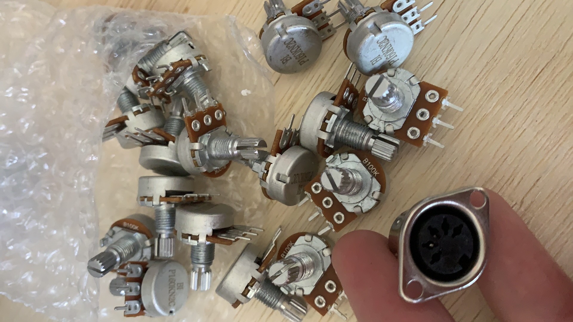
Potentiometers
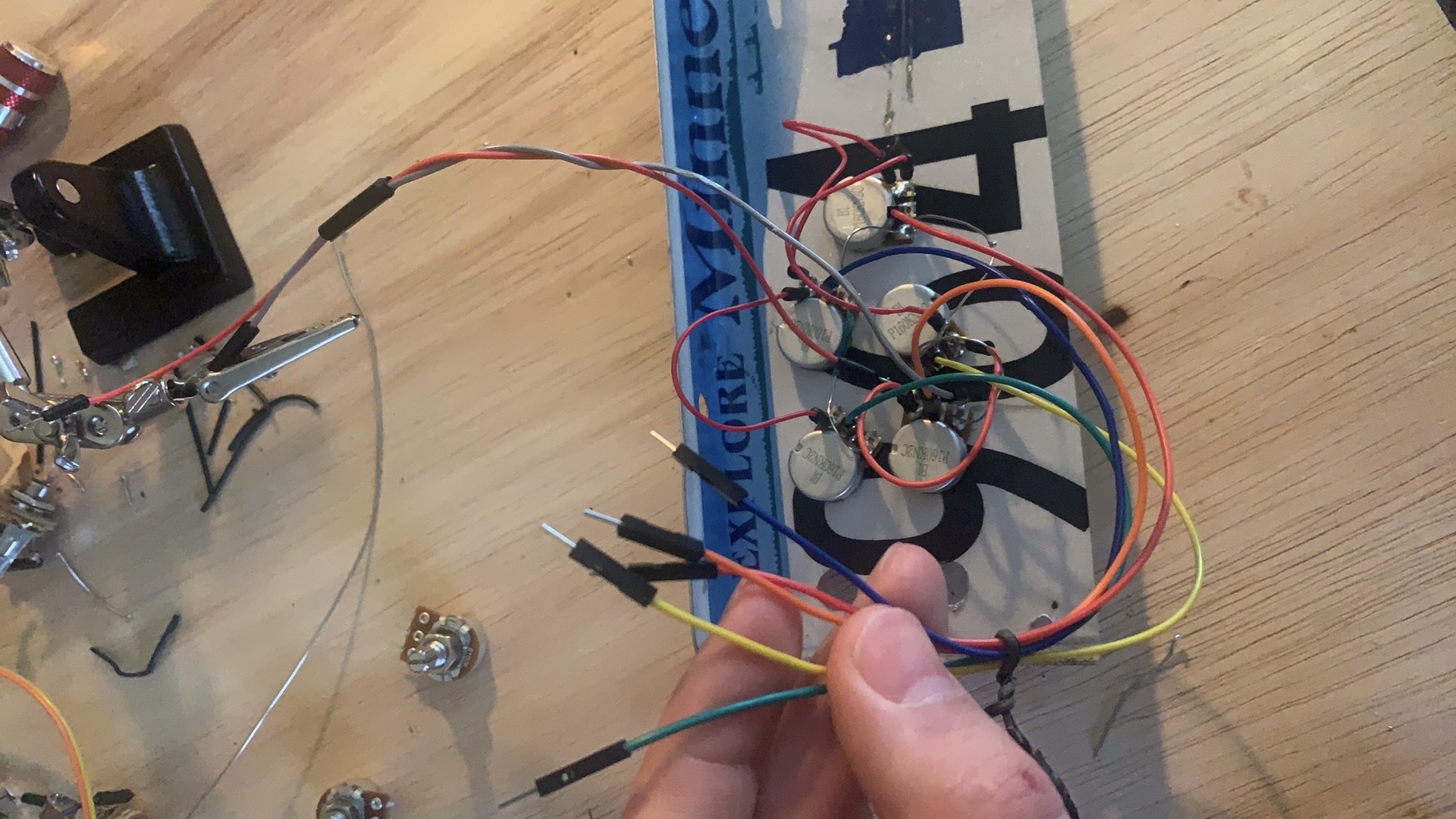
Internals Mounted on License Plate Control Panel
Keyboard
- Keyboard Input
- Keyboard
- Keyboard On/Off
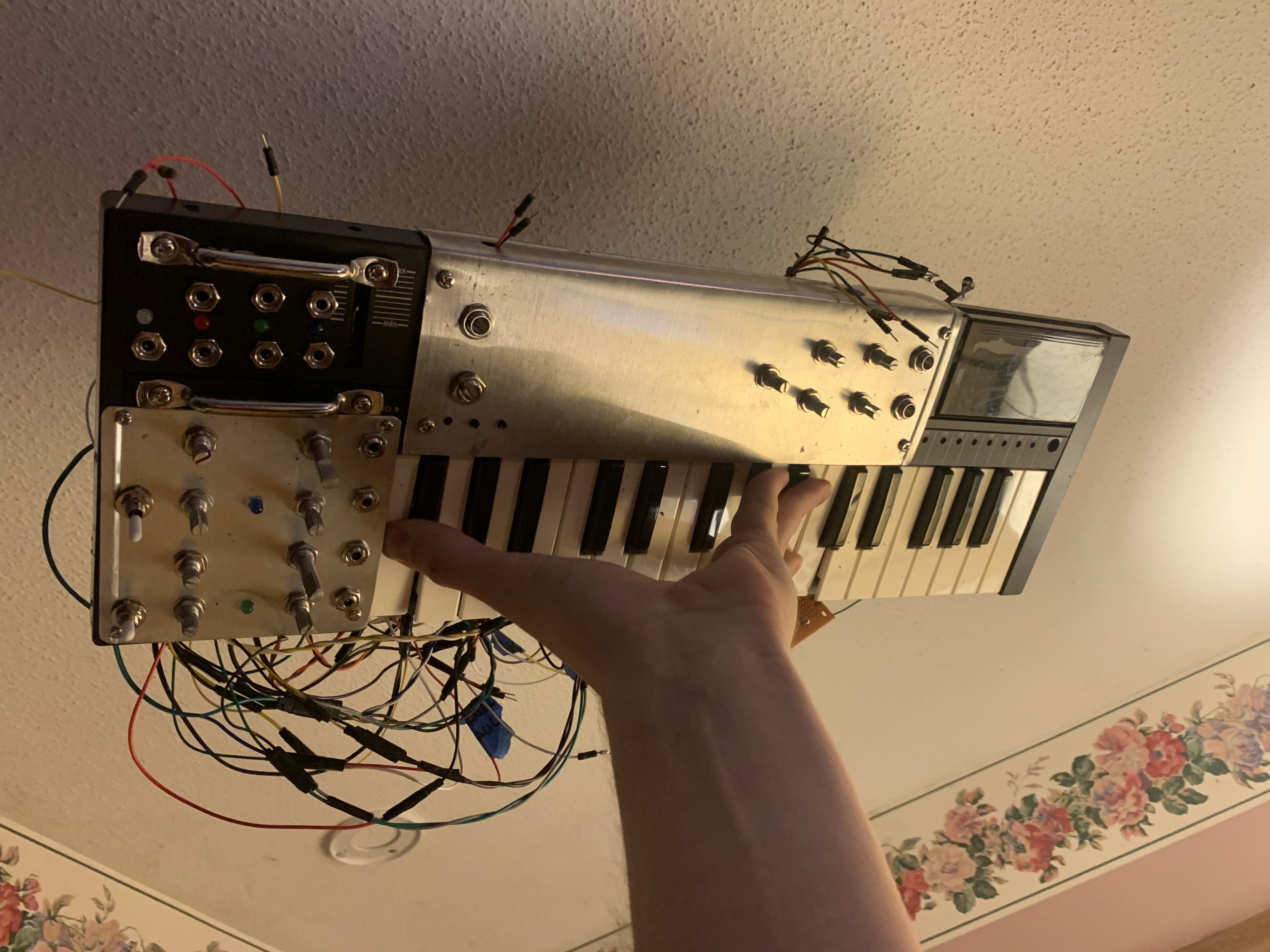
The keyboard on this unit is fully functional but is not active by default. To route voltage through the keys, you must patch one of the onboard oscillators (or an outboard one if desired) into the input jack. The keyboard operates as a chain of resistors in series acting as a ladder for scaling voltages depending on which key is pressed.
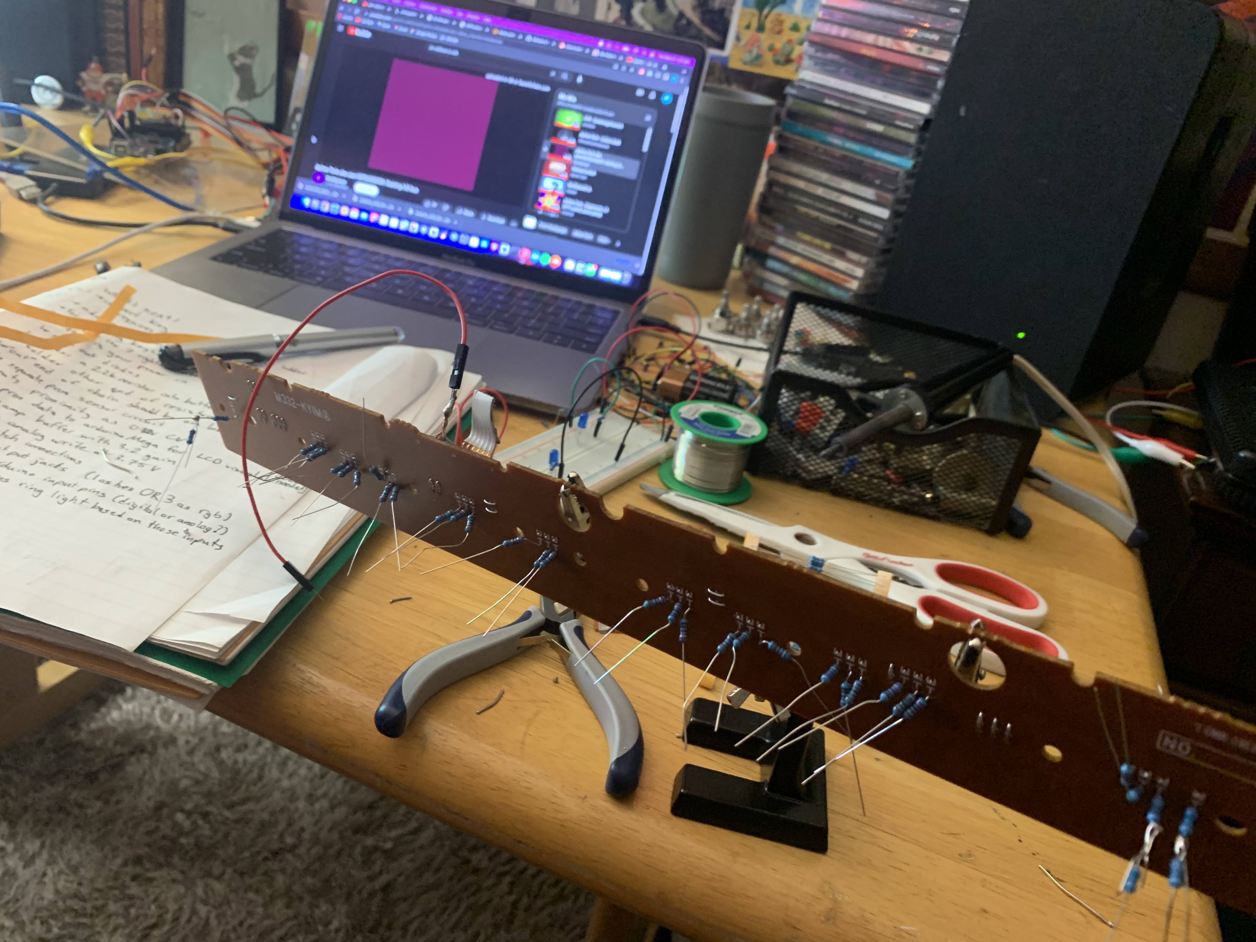
Resistor Ladder Keyboard
Display Monitor
- Proximity/Color Sensor Monitor
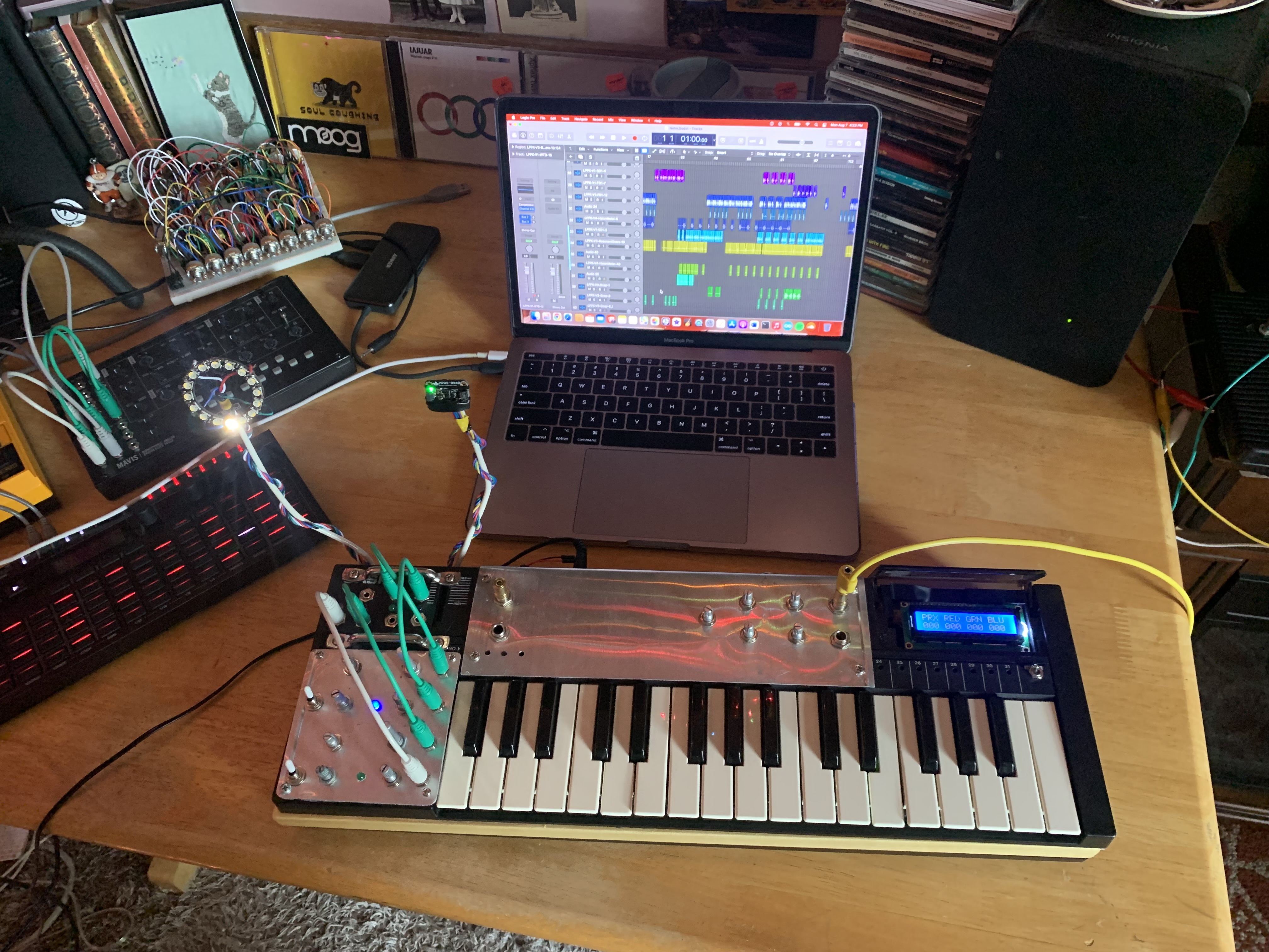
This monitor is powered by an Arduino Uno that receives inputs from the separate microprocessor which drives the sensors. Displayed on this screen are the values for Proximity, Red, Green, and Blue, currently being read by the Adafruit ADPS-9960 sensor. The monitor serves not only as a point of reference for value levels, but also as a troubleshooting tool.
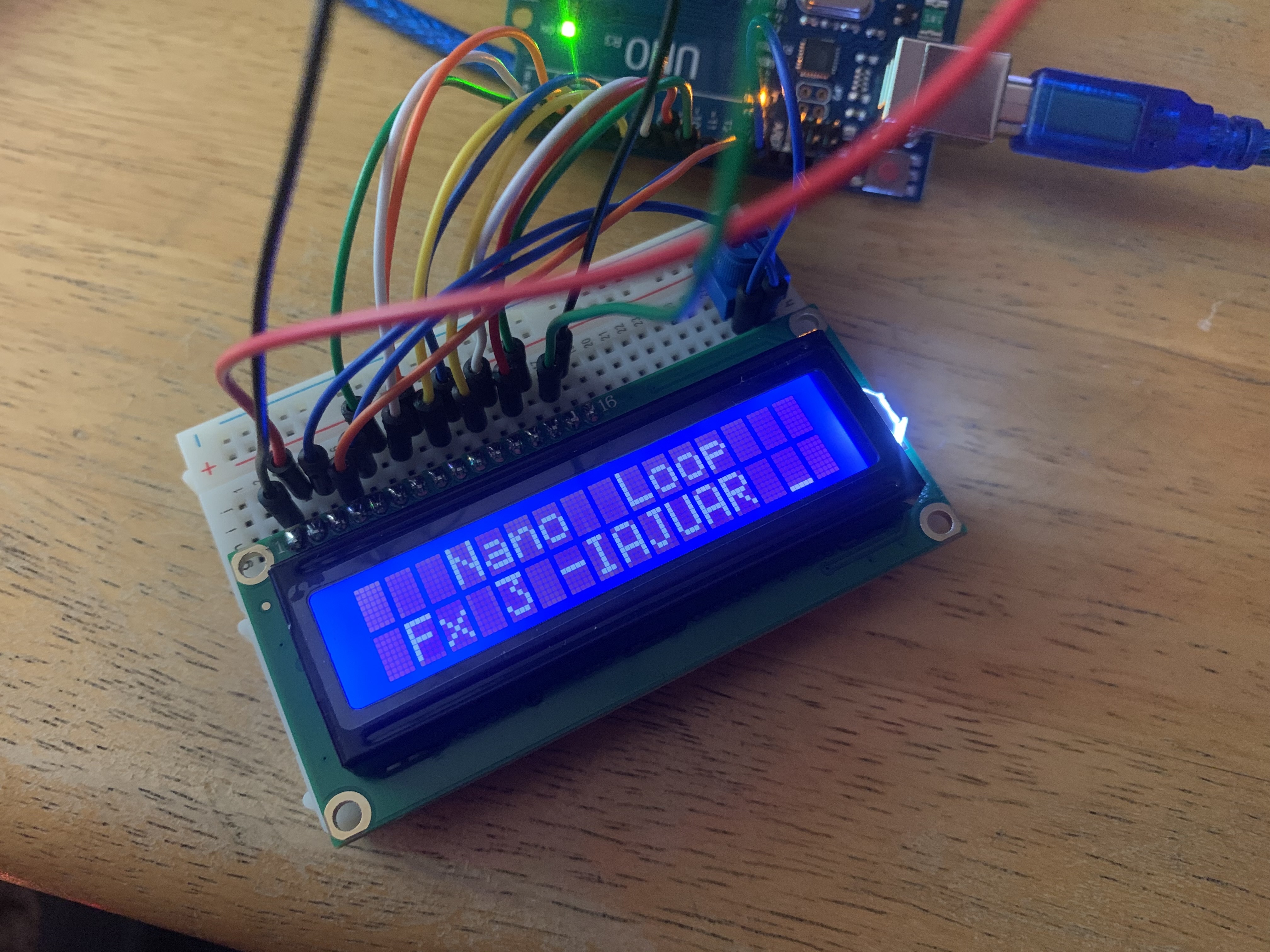
LCD Monitor Test
Auxiliary Designs
Developed in tandem with the synthesizer above, these designs connect with its analog capabilities and expand its functions offboard.
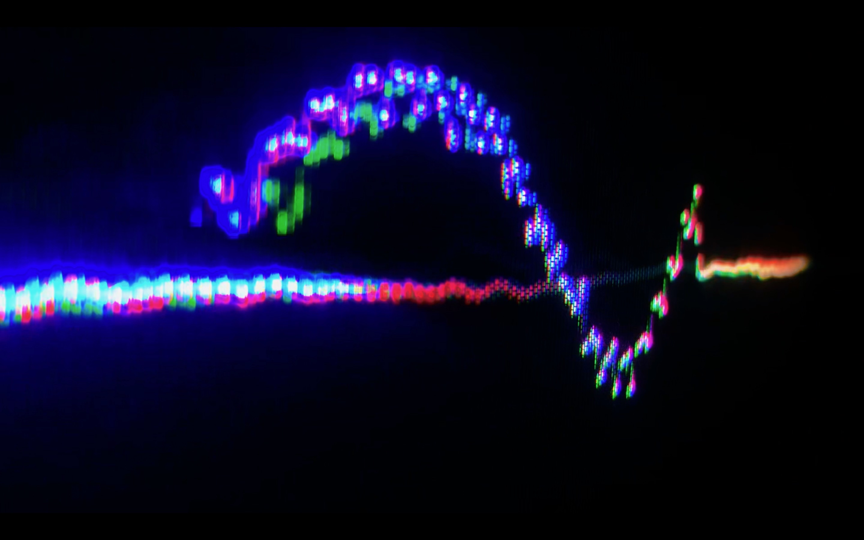
CRT Oscilloscope
In developing oscillators, a common troubleshooting method is using an oscilloscope to tune and inspect waveforms. These oscilloscopes can be expensive and inconvenient, but luckily with some tweaks to the circuitry, a DIY alternative can be made using the hardware of a Cathode Ray Tube found in an old TV.
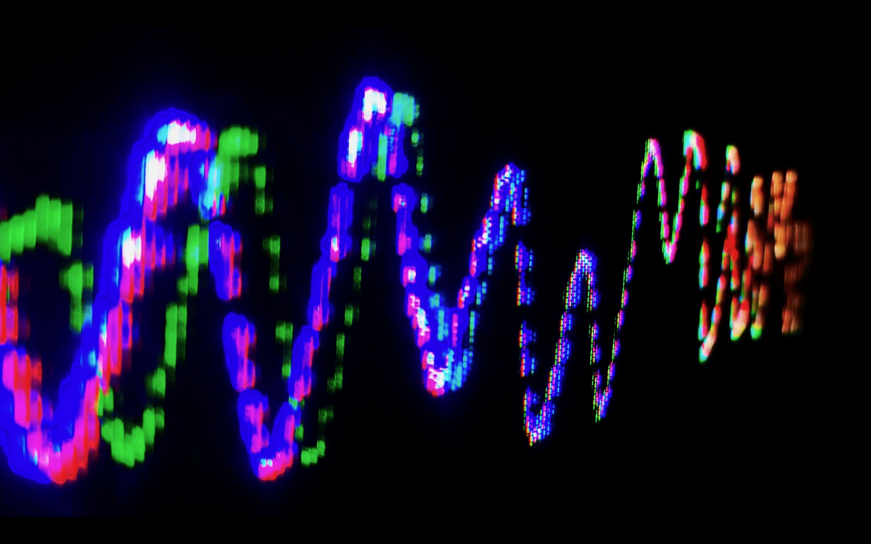
Soundwave DEMO 1
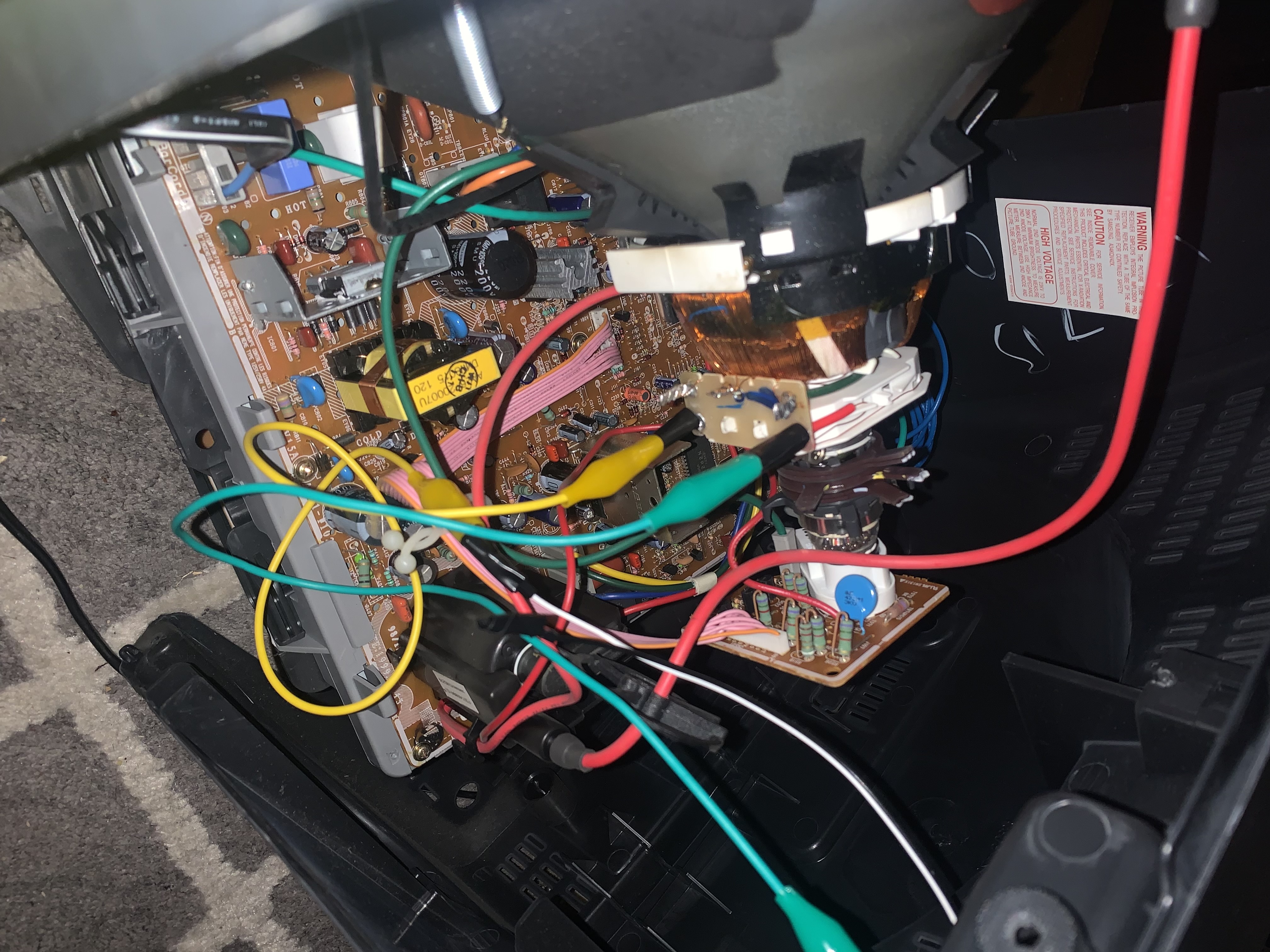
CRT Internal Modifications
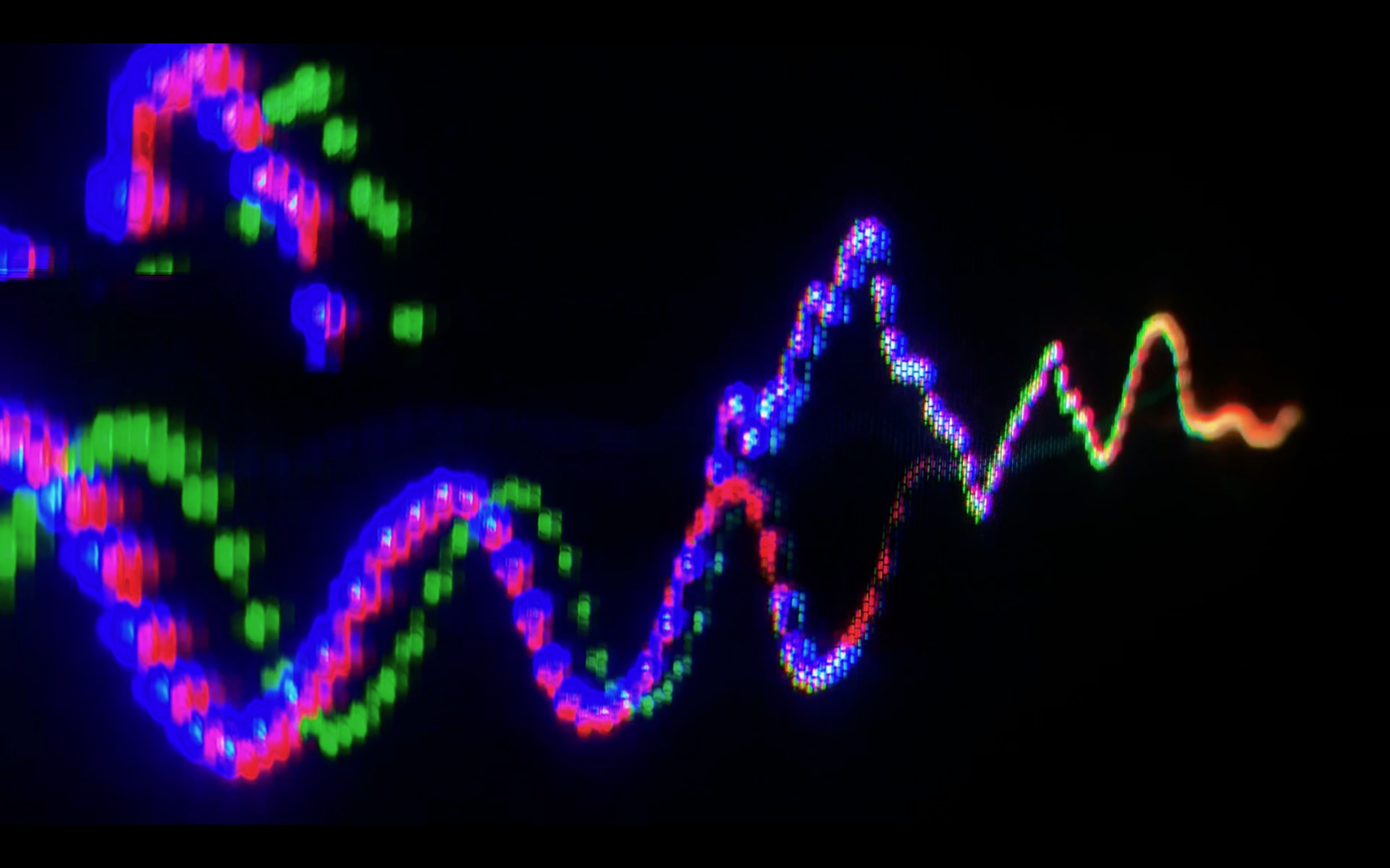
Soundwave DEMO 2
Saw Wave OSC Test
Soundwave DEMO 3
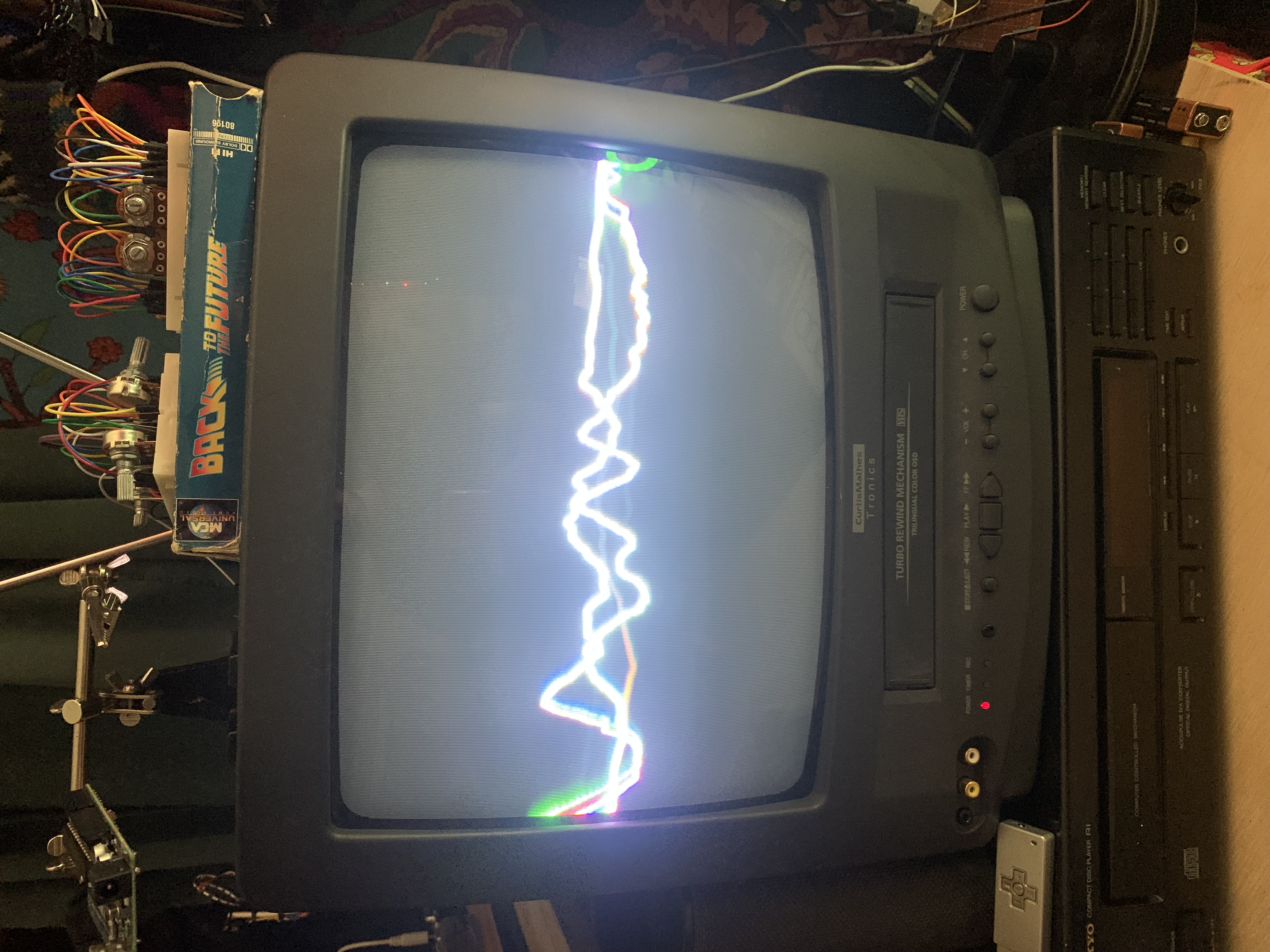
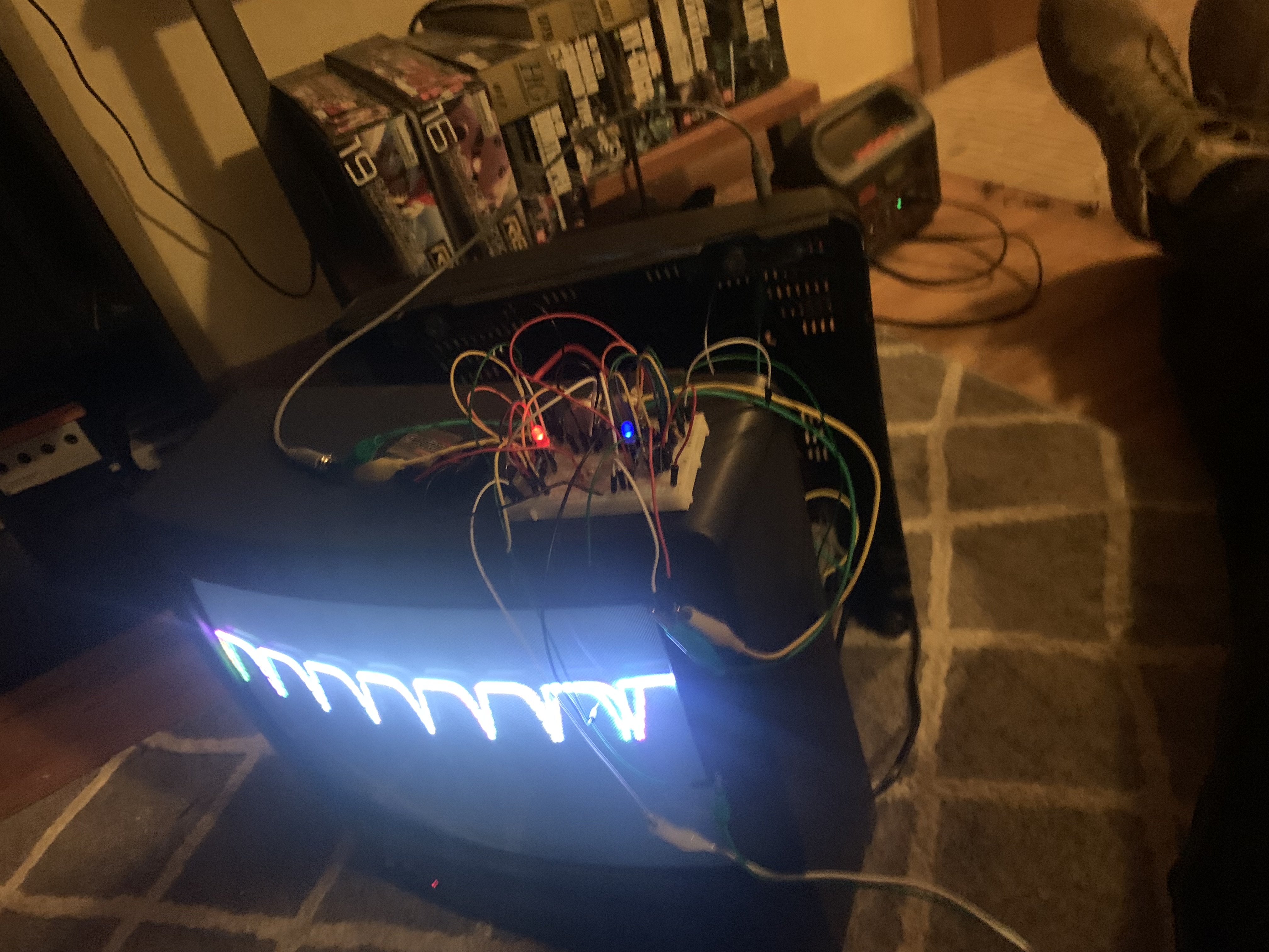
Complete TV
Square Wave OSC Demo
Track Visualizer Demo
Void.Loop+ Visualizer
Step Sequencer
A fully analog 16 step sequencer constructed around the CD-4017 decade counter IC and NE-555 timer IC. This project can cutoff and loop at only 8 steps or be patched so that the first CD-4017 cascades to a second and count to a full 16 steps. Originally meant to be included within the synth but internal spacial scarcity forced this project to remain outboard.

Step Sequencer Demo
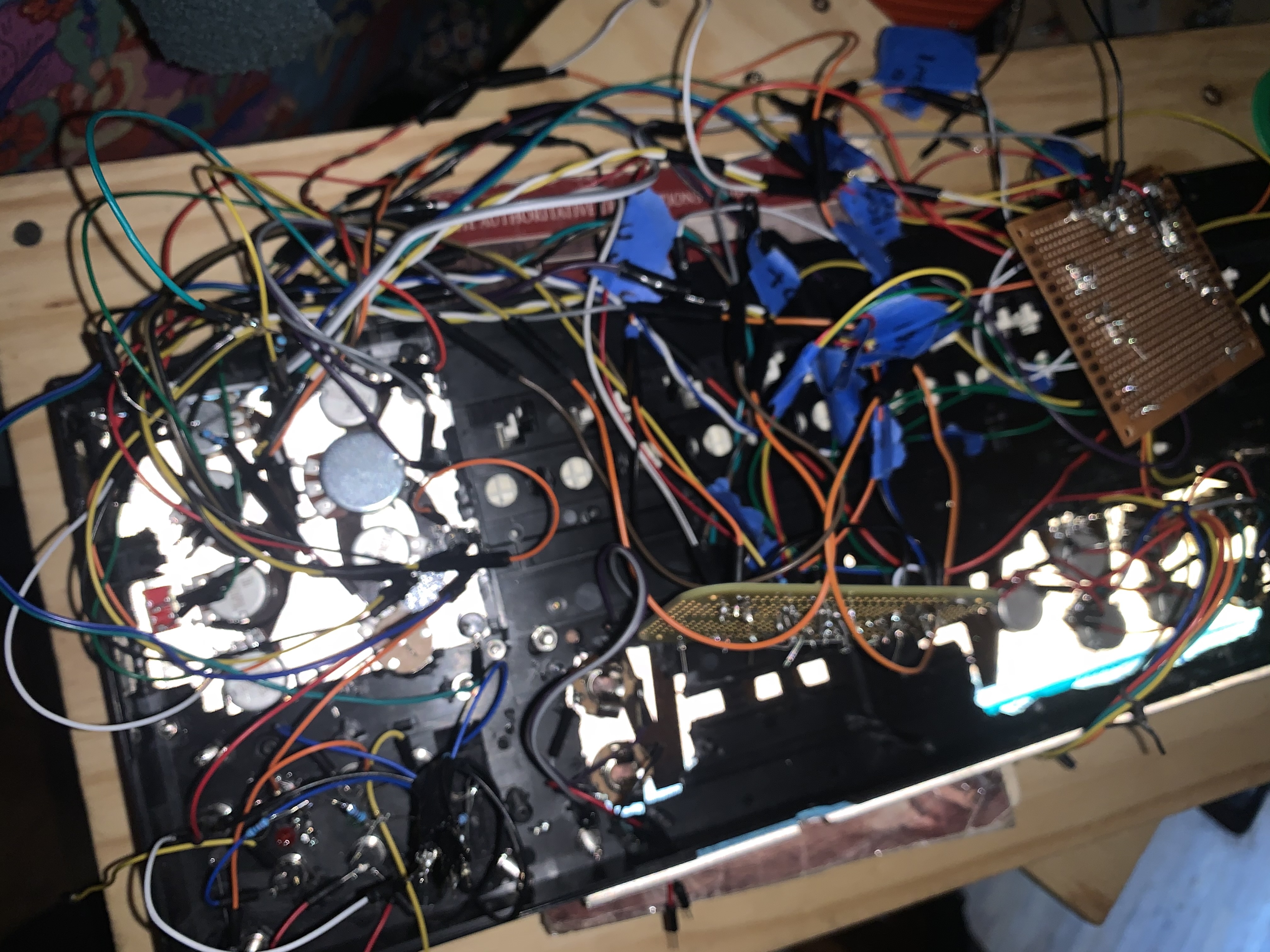
Circuit Bending
Circuit bending keyboards reveals glitches and unpredictable behaviors by short-circuiting or rewiring their internal components. On this Casio I have removed part of the casing so that the main logic board is exposed and have also added two potentiometers and one switch. the potentiometers and switch are grounded internally into the native circuitry but their positive end is hooked to an alligator clip which can be attached to different pins on the now exposed logic chip in differing combinations. Attached to the right pins, the registers of the board can be flooded with corrupted data at the flip of a switch and then tuned with the potentiometers. Pictured below is the Casio along with a Yamaha keyboard which also received the same preparation
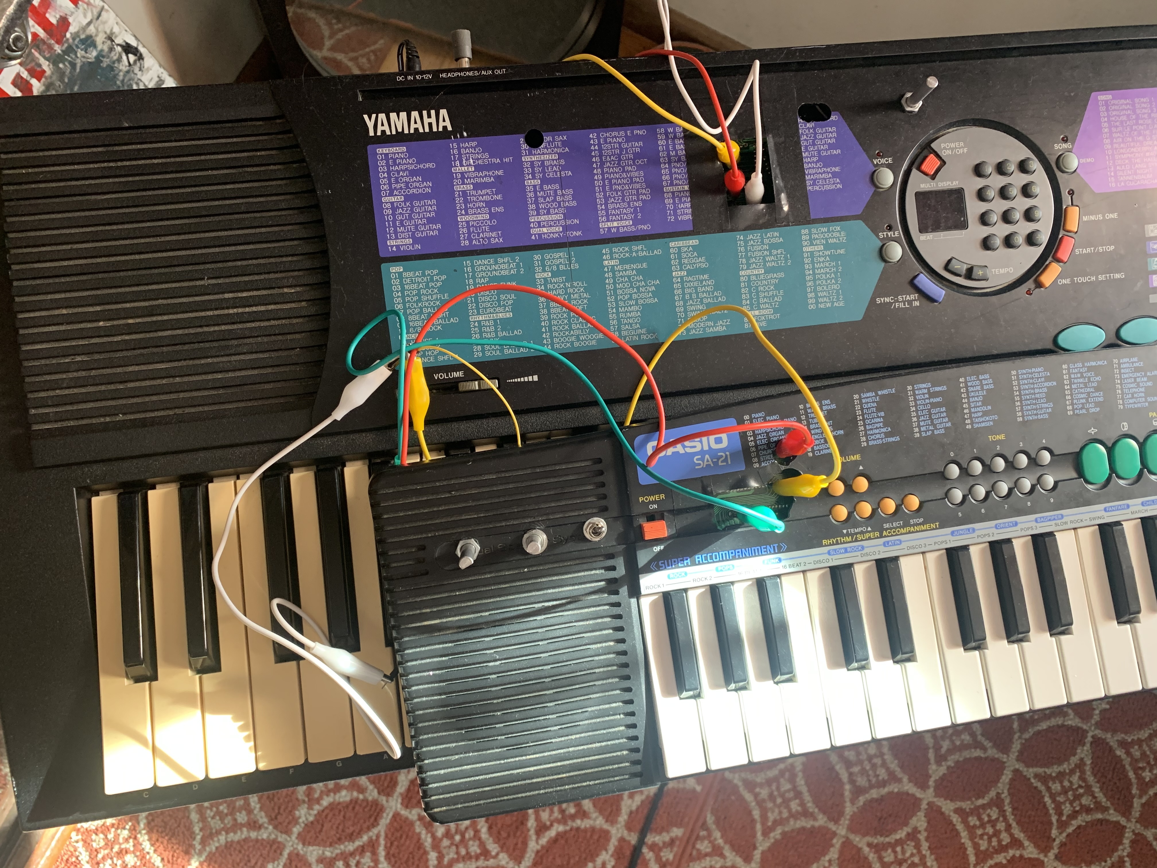
Circuit Bent Casio and Yamaha
Circuit Bent Casio DEMO